Back to article
3348
*Default setting shown. To modify the house code of the system, see Changing house code settings.
**These switches function as part of the house code when MDU mode is enabled. For more info, see Setting MDU mode.
Setting up your product
Learn how to set up your product, connect components and enjoy the benefits of all its features.
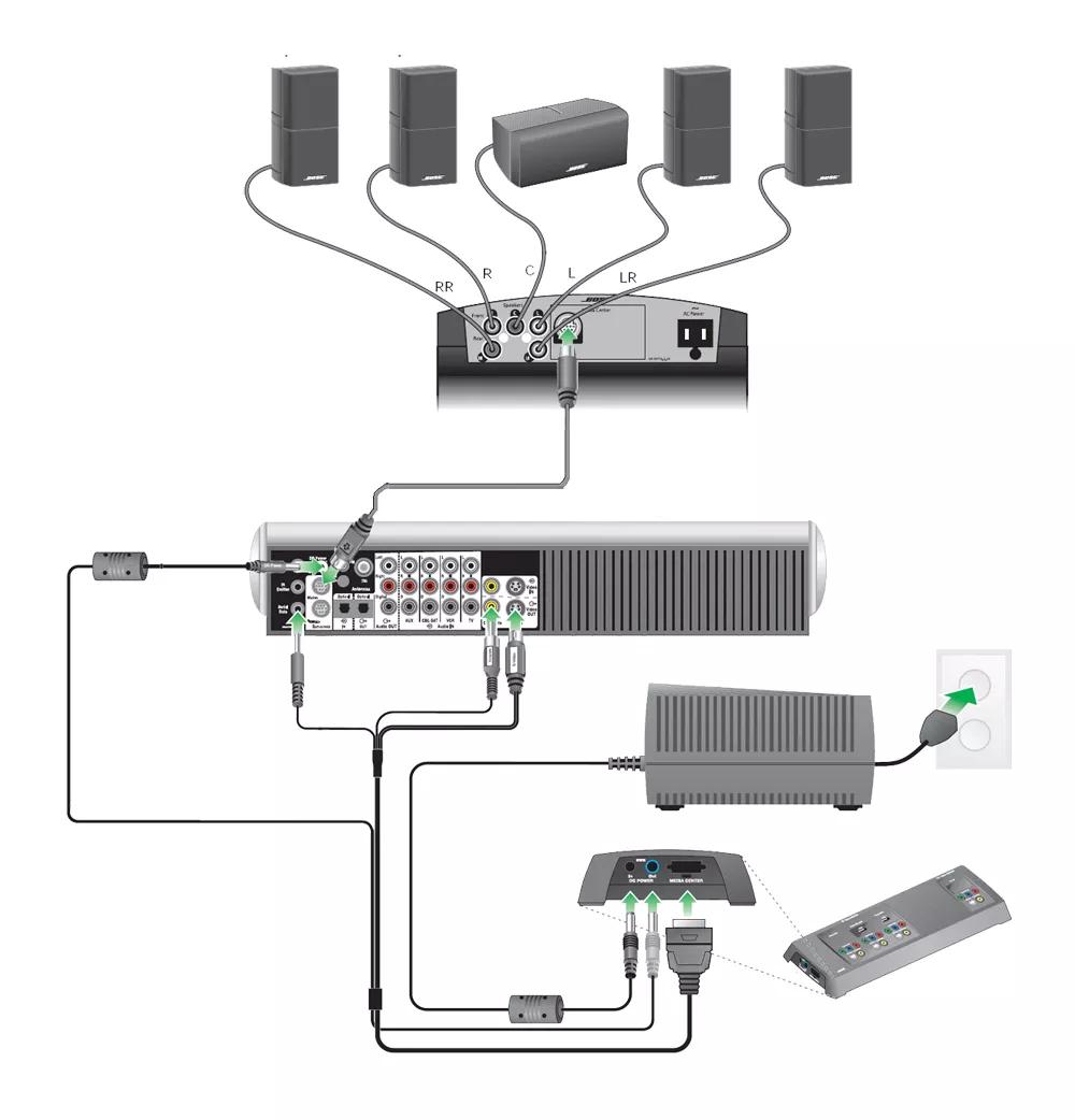
To connect the components of your system:
- Connect the audio input cable from the Main jack on the system console to the Audio Input jack on the bass module
- Connect the speaker cables from each speaker to the Outputs to Cube Speakers jacks on the bass module
- Connect the power cord from the bass module to an AC (mains) outlet
- Connect the 4-plug end of the VS-2 video expander cable to the system console:
- Connect the Serial Data plug to the Serial Data jack
- Connect the DC Power plug to the DC Power jack
- Connect the Composite Video plug to the Composite Video OUT jack
- Connect the S-Video plug to the S-Video OUT jack
- Connect the other end of the VS-2 cable to the VS-2 video expander:
- Connect the multi-pin plug to the Media Center jack
- Connect the power plug to the DC Power Out jack
- Connect a video cable (HDMI, Component, S-Video or Composite) from your TV to the Video OUTPUT secdion of the VS-2
- Connect your video devices (i.e. cable box, DVD player, etc.) to the Video INPUT jacks on the VS-2
Tip: The input connections cannot be a higher quality connection that the output connect to your TV. The connection quality from lowest to highest is Composite, S-Video, Component, HDMI - Connect the power supply to the DC Power In jack on the VS-2
- Connect the power supply power cord to an AC (mains) outlet
Determine where to place your product.
For speaker placement suggestions, see Speaker placement and positioning.
RC18, RC38, and RC1V Main Room Remote DIP Switch Settings
| Switch Label | Setting | Switch Function |
|---|---|---|
| 1 | Down* | House code |
| 2 | Down* | House code |
| 3 | Down* | House code |
| 4 | Down* | House code |
| 5 | Down | Audio stream |
| 6 | Down | Room code** |
| 7 | Down | Room code** |
| 8 | Down | Room code |
| 9 | Down | Room code |
**These switches function as part of the house code when MDU mode is enabled. For more info, see Setting MDU mode.
Using in-wall speaker wiring.
Note: Due to the variety of state and local building codes concerning in-wall wiring, the wiring supplied with Bose systems may or may not be acceptable for in-wall installations. Check local codes for details.
If your room has speaker wires installed in the walls, the accessory Adapter Kit for In-Wall Speaker Wires is available to connect to your existing speaker wires
If your room has speaker wires installed in the walls, the accessory Adapter Kit for In-Wall Speaker Wires is available to connect to your existing speaker wires
Run ADAPTiQ to maximize the system sound.
For more information on how to run ADAPTiQ, see ADAPTiQ system setup and deactivation.
The ADAPTiQ audio calibration software, included with the system, automatically tests the acoustics of the listening area, analyzes speaker placement and tailors the sound of the system to the specific acoustics of the room.
The ADAPTiQ audio calibration software, included with the system, automatically tests the acoustics of the listening area, analyzes speaker placement and tailors the sound of the system to the specific acoustics of the room.
Connect audio devices to your product.
For more info, see Connecting other devices to your system.
Was this article helpful?
Thank you for your feedback!